
In the previous chapter we discussed how devices communicate with each other that are physically close to each other or are even on the same PCB. The communication in these scenarios are quite protected and thus work with a minimal overhead.
Devices that are far from each other need communication that is robust and enables devices find each other in large networks.
RS-232
RS-232 is the “Serial Port” on your computer and was originally designed to implement the communication between a Modem and a Computer. As this standard was really successful it widely spread and computer mice were using this standard for quite a long time, microchip programmers, various peripheral devices or if you are old enough you can remember connecting PCs together with the Serial Port playing DOOM.
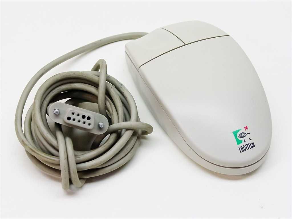
Serial Port Mouse – Credit: Twitter/Foone 
DOOM Serial Port Settings – Credit: doom2.net 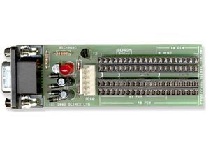
PIC Programmer – Credit: 320volt.com
The RS-232 standard is the definition of a physical interfacing methodology, the communication itself is based on UART and is extended in a way that it is capable of more robust communication and also enables flow-control. The goal of the flow-control is to make sure the receiving party can process the data at the pace it is being sent. Looking at the 9 pin DSUB pinout RS-232’s relation with modems is something quite obvious. The original standard defines a 25 pin DSUB connector, at the same time recently the 9 pin versions are used more often.
The flow-control is implemented with the following pins:
- RTS – Request to Send: The transmitting party notifies the receiver with a “high” value that it would start a transmission
- CTS – Clear to Send: The receiving party notifies the transmitting device that it is ready to receive data
- DTR/DSR – Data Terminal Ready/Data Set Ready: These lines can be used in a similar way like the RTS/CTS signals to implement flow-control. In elder devices these signals were used by the devices to notify each other that they are operational. In other cases these pins were used to supply power for the devices. RS-232 is an old standard so many variations were created over the years.
- RI/DCD : Ringing Indicator/Data Carrier Detect: These signals were used with modems and are tightly related to telephone networks.
There are other software based flow-control implementations where special characters are sent that mark flow-control events.
We already discussed the RX/TX lines in the UART section. These are the Receive Data (RD) and Transmit Data (TD) pins in the diagram above. Just like with UART having separated TX and RX lines also mean full-duplex data transfer.
It is important to note that in many cases there is no need for flow control. In these scenarios we can operate with 3 cables as shown in the diagram below.
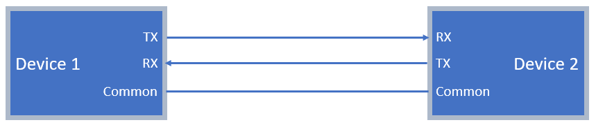
On the physical layer the RS-232 uses higher voltage levels than the UART which improves robustness.
Among the many benefits of the RS-232 communication one significant drawback lies: RS-232 is a point-to-point communication, it other words only two parties can be present. There are similar standards that enable multi-point communication. One of the most popular ones is the:
RS-485
Similar to the RS-232 standard the RS-485 only defines the physical interfacing methodology and the communication itself is based on UART in many cases.
RS-485 is widely used in the industry to chain transducer on larger areas and it is also used in home automation, for example in intercoms to handle the dial and ring signals.
As the RS-485 is a multi-point communication platform it is possible to implement various topologies. The standard recommends a linear layout where devices are chained together with termination resistors around 120 Ohms. In the diagram below only 2 wires are shown. According to the standard there should be a “Common” wire as well but RS-485 works without it.
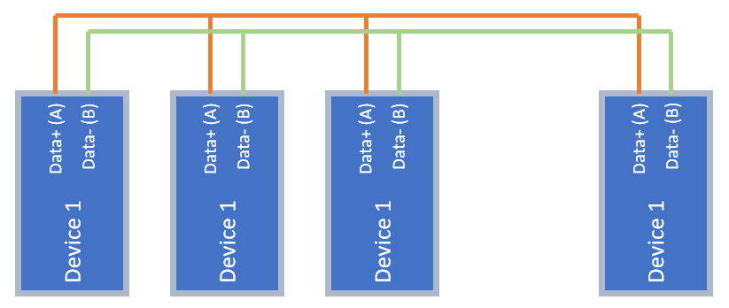
The network setup above shows a two wire setup which means that we talk about a half-duplex communication. There are other setups where 4 data cables are used instead of 2 that enables full-duplex communication.
Now that we have multiple devices we need to take make sure that devices know when they are allowed to “speak” not to interrupt other devices. In other words we need to implement arbitration. A described before RS-485 is the definition of a physical interface and is not responsible for arbitration and it is implemented in a higher level. This is thus a perfect time to talk about:
Communication Abstraction Layers
Let’s take the example of reading a temperature sensor with an Arduino, scaling the values, sending it to the computer and then displaying the results on the screen. However this task is relatively easy with modern programming environments and devices there are a huge number of steps involved in this process:
- Communicating with the sensor via I2C
- Setting internal registers to configure I2C speed
- Configuring address length
- Checking what is the status of the internal state-machine that handles the I2C interface..
- Executing the math related to scaling the values
- Moving the I2C data from one register to an other
- Executing mathematical expressions
- Storing results in the memory
- Communicating with the PC from the Arduino
- Setting up the internal registers that control the serial communication
- Sending data byte-by-byte to the sending buffer
- Checking the status of the internal state-machine
- Interfacing with the IC on the arduino board that handles serial communication over USB..
- Displaying data
- Receiving data over USB
- Converting this data as a virtual serial port
- Handling memory to append received bytes and reconstruct the send message
- Interfacing with the video card in the PC to set the value of various pixels
- Handle interrupts coming from HMI devices to track user interaction
- Monitor power management of peripheral devices…
And this is actually just a fraction of the things happening in the background. What I wanted to show is that doing everything on such a low level and starting from scratch each time would make it close to impossible to accomplish complex tasks. If we work on a task we expect to be able to focus on the actual things we want to implement and work with other components according how they are specified to work. These other components are called abstraction layers.
To be able to implement our application in a specific layer we only need to know how to interface with the layers below and above. We also know what those layers do but we do not care about how they work.
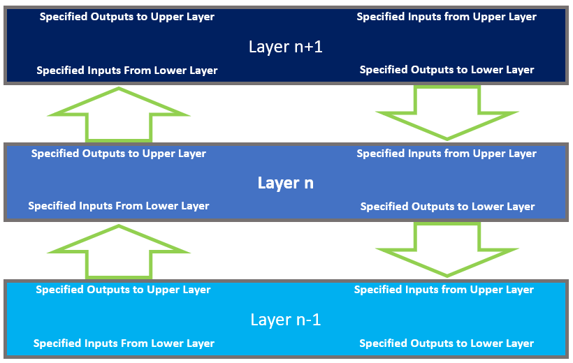
When talking about abstraction layers in communications the most commonly used model is the OSI (Open Systems Interconnection). There are many IEEE and IEC standards governing it but we are not going to go into details about those.
Even if you have not heard about the OSI model you have been enjoying its benefits. As an example every time you are using an HTTP request you are operating on the top layer of the OSI model and took it for granted that all the layers below it work well. The next picture shows how the OSI model is architectured.

Arbitration
Now back to the topic of arbitrating on an RS-485 network. There are various ways how to implement arbitration, now we are looking into a common solution: a master-slave architecture. There is one master device on the network who coordinates the communication: it is asking the slaves one by one to report back on various parameters and the slaves cannot talk without being asked. By doing so it is easy to avoid network nodes interrupting each other. An often used standard that defines how the network nodes exchange information on the RS-485 network is Modbus.
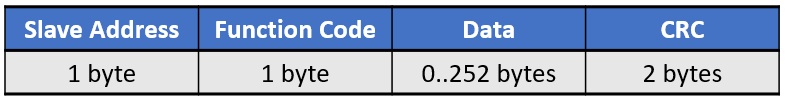
Modbus defines a message frame format to standardize addressing, sending payload, error checking. Modbus application layer thus operates in the 7th Layer of the OSI Model.
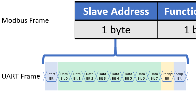
At this point it is a great opportunity to show how layers build on each other. Remember the Framing we discussed in the UART section? Well, the Modbus Framing is one level higher, so each byte in the Modbus frame is actually an UART frame. The UART frame is operating in the 2nd Layer in the OSI Model. In this case it is actually called Modbus Serial Line protocol.
Modbus works in a way that:
- We tell all the nodes who we want to speak with – this is the address. Each node has a unique address.
- The Function Code tells the node what we want to do: write data, read data, what type of data etc..
- Then the Data itself contains the information we send to the node or the information sent by the node
If you look at the Modbus framing format you could question: what blocks us from using Modbus with RS-232 or even Ethernet? Well the answer is nothing!
X over Y
As stated above Modbus protocol can exists on RS-485 networks, RS-232 networks or even Ethernet.
So a Modbus network implemented over an RS-485 network is called Modbus over Serial or Modbus over RS-485. In case of Ethernet it can be called Modbus over Ethernet.
In general if a higher layer in the OSI model can work above various protocols on lover levels we use the term “over” to specify which one we are referring to.
Even more it is possible to implement protocols in the same layer “over” each other with some virtualization:
- The USB port on the ESP or Arduino devices is practically a “Serial over USB” port.
- USB connections can show up in your computer as ethernet ports. These are “Ethernet over USB”
- There are devices that act like serial port extenders that connect to your computer. These are Serial over Ethernet devices.
Not so known protocols
In this segment I would like to mention a few communication standards that are not so well known at the same time are really interesting and might be useful for you to know about:
- CAN (Controller Area Network): This protocol is the de-facto standard in the automotive world. Majority of the units in your car communicate over CAN. It is really robust, operate with two wires and the arbitration implements prioritization by default. It is also used in home automation. The Loxone Link is also a CAN network on the physical layer.
- LIN (Local Interconnect Network): This is an other standard often used in the automotive world. LIN is based on the UART communication definition but is more rugged on the physical layer.
- FlexRay: Also an automotive network type. FlexRay operates over two twisted pairs and its most unique feature is the speed and determinism. A FlexRay frame consists of various slots (dynamic and static ones). The master starts a frame and expects the nodes to place their data into their slot in the specific frame. This enables for example an ESP controller to acquire data from the wheel speed sensors and provide a control signal in the very same frame!
- SENT: When talking about the low level communications we discussed that bitrate and baud rate is not the same. In SENT protocol the information is carried in the length of pulses – 16 different lengths can be differentiated in a symbol called “nibble”. Thus the SENT protocol carries 4 bits in 1 baud. SENT is often used in small automotive sensors.
Ethernet
Ethernet is a very widely used communication protocol that implements the 1st and 2nd layer in the OSI model. The really attractive features of Ethernet are versatile network topologies, error correction, various physical media types, high data transfer speed, great trade-off on latency.
Network topologies and routing device are a large topic and can get very complicated so we are not covering them in this segment. We are focusing on Ethernet’s role in the OSI model.
Ethernet practically operates in two layers of the OSI model:
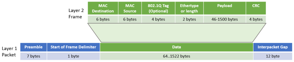
In some documentation you will find “octet” instead of bytes. The reason for this is that in certain computer platforms a byte is not 8 bits, while an octet is always 8 bits.
MAC (Medium Access Control )addresses are the identifiers of the network devices, this is how they find each other in the network.
Zooming out from the bottom two layers in the following diagram you can see the Internet Protocol Stack:
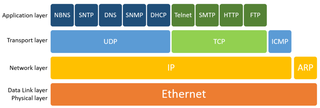
Focusing on the Network layer:
- ARP (Address Resolution Protocol) – This is responsible for mapping MAC addresses to IP addresses
- IP (Internet Protocol) – Defines how the information is assembled as an IP packet to be sent over the network.
The standards in the higher layers will be discussed later on in blog posts as discussing them can get really long.