
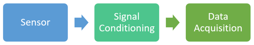
So a sensor’s main purpose is to convert a physical phenomenon, quantity to an electric signal that can be somehow connected to a signal conditioning, then data acquisition device. It is important to understand how a specific sensor works so we can select the best signal conditioning and measurement method that give us the best results.
There are thousands of type of sensors and they are often used in combination with each other or implementing different measurements, for example precision distance measurement by measuring pressure, measuring vibrations by displacement, etc.. In the list below we are learning about the most common sensors and with a very high-level overview. The goal here is that by a 15 min read you can get up to speed with sensor. Should you be interested in more details just do some google search – they are very well documented.
Temperature Sensors
Temperature sensors convert temperature to electric signals. The two most commonly used temperature sensor types used in DIY IoT devices are:
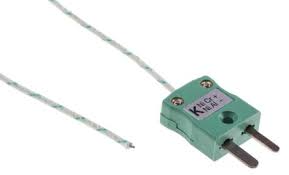
- Thermocouples: If you connect two types of metals together then there is going to be a small voltage at the junction of the two pieces. This voltage is the function of the junction’s temperature for a certain metal pairs. The name of the sensor tells you what metals are used (for example Type “K” is cromel-alumel). Different types can cover different temperature ranges, Type “K” is a good choice for DIY home automation projects as it is cheap and covers a reasonable temperature range.
- Pros:
- These sensors can be lightweight so they react quickly to temperature changes.
- They are relatively cheap.
- Can cover large temperature ranges.
- In the commonly used temperature ranges they are quite linear. It means that a twice as hot temperature result nearly twice as high voltage. So it is easy to process the result.
- Cons:
- The voltage they produce is really small ~10mVs so you need signal conditioning (amplification) of the signal before measuring it.
- If you think about it when you connect a thermocouple to your device then two additional thermocouples are created at the connection points of the wires and your screw terminals. When measuring your temperature in the living room it doesn’t matter but in professional application they do CJC (Cold Junction Compensation) which means that they measure the temperature at the connection points and use it to correct the measurements.
- Pros:
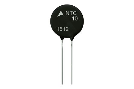
- Thermistors: Resistors’ resistance value changes as their temperature changes. In electrical circuits this is an effect that you try to minimize with various tricks as they can distort the signals in your circuit. Except if the goal is to measure the temperature! Thermistors are special resistors that are designed in a way that they significantly change their resistance due to temperature changes so to measure the temperature you simply need to measure the resistance itself. There are two types: PTCs (Positive Temperature Coefficient) and NTCs (Negative Tempreature Coefficient). To simply put if you increase the temperature then PTCs will increase their resistance while NTCs will decrease it.
- Pros:
- The signal conditioning circuit is very simple because you can use thermistors as voltage dividers
- Cons:
- Smaller measurement range than thermocouples
- Non-linear measurements, so it is complicated to calculate the temperature value from the coltage
- In most cases they are not very precise
- Pros:
Light Sensors
Light Sensors convert light intensity to electric signals. When you select one based on the specs always look for wavelengths. This parameters tells you what type of light they are sensitive to. For example you need different types for checking if the sun is shining and to check the presence of a laser beam. The two most commonly used ones are:
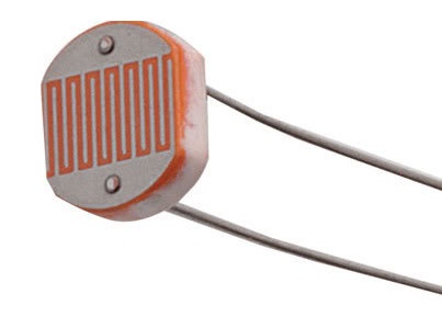
- Photoresistors: These devices are basically resistors that change their resistance based on how much light they are exposed to. The packaging usually is a circular plate and one side is sensitive to the light. It is important to note that they are tuned to be sensitive to certain frequencies so when you order one you should more or less already know what type of light you want to sense.
- Pros:
- Low price
- Easy integration into circuits – you can build voltage dividers
- Cons:
- They are not extremely sensitive so you need quite a significant difference in lighting to produce a real difference in resistance
- Compared to photodiodes they react slower to changes in light intensity
- Pros:
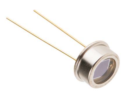
- Photodiodes: General diodes are special electric components that let the current flow into one direction but doesn’t let it flow the other. The basic principle of operation is that in a semiconductor crystal two regions are created one of them with too many and the other with not enough electrons (compared to the their natural state) and this results that the area where the two regions meet (called depletion region) is not conducting electricity by default. However if you apply a voltage from one direction (so there is an electric field) then the depletion region will be more or less populated and thus current can flow through. But this only works in one direction! Photodiodes work in a way that instead of applying an external electric field (in photovoltaic mode) the photons kick off some electrons in the depletion region and the empty locations start to migrate thus a small current is generated, called photocurrent. Photodiodes can operate in three ways:
- Photovoltaic Mode: You simply measure the generated photocurrent current. This is really small so you need very good measurement devices.
- Photoconductive and Avalanche Diode Mode: A reverse voltage is applied onto the photodiode so normally it doesn’t conduct. When photons hit the depletion region then being biased the effect of the kicked off electrons can mulitply itself (hence the name “avalanche”). The physics here is quite complex, for us the important information is summarized here:
- Pros:
- Very sensitive to even small light changes
- Are very fast compared to Photoresistors
- In professional instrumentation they are used as for enabling precise measurements
- Cons:
- More expensive than Photoresistors
- If you don’t want to use in On/Off mode but do measurements then you need very good Signal Conditioning and Data Acquisition
- Pros:
Strain, Force, Pressure Sensors and Accelerometers
In instrumentation these sensor types usually are correlated to each other and we will discuss below why. Let’s start with force.
Force Sensors
Force sensors convert physical force to electric signals. There are multiple types of them:
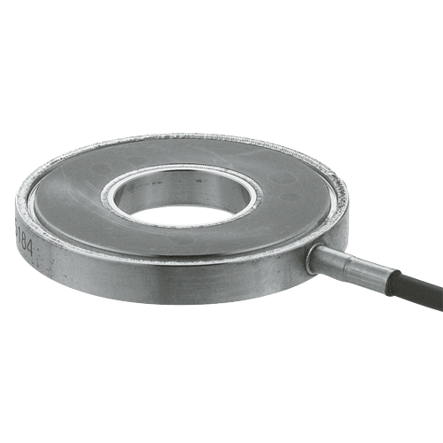
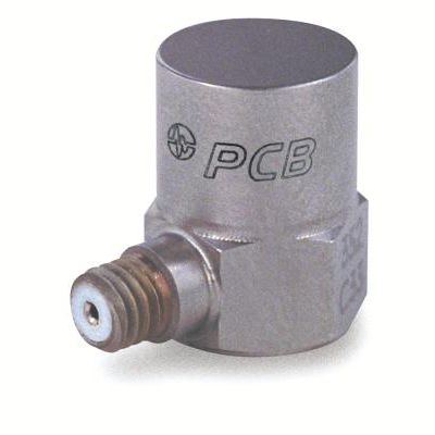
- Piezoelectric sensors are based on special, so called piezoelectric crystals. Piezoelectric crystals generate a very small current (practically just some electric charge) when a mechanical force is applied to them. And they also work in the opposite direction: if you apply some current through them they change their size/form. This is how the treble speakers work in many loudspeakers. For the vibration measurements we use the electrical current by physical force method. So to measure the force all you need to do is measure the current (electrical charges) generated by the piezo sensor. The small current is converted to a properly measurable voltage with a special electric circuit that usually is integrated into the sensor itself. These are the IEPE (Integrated Piezo-Electronic) sensors. In order to operate the integrated circuits need a constant current source supplied via the measurement cables.
- Pros:
- IEPEs are easy to use
- Lightweight versions can be mounted with a piece of wax or magnet
- Multiple sensitivity ranges
- Cons:
- Pretty expensive, also the needed data acquisition device
- IEPEs’ operating temperature range is limited do to the integrated circuit
- You cannot measure static force with them. The current is only generated by the piezo crystal while the deformation, the force happens.
- Pros:
- Piezoresistive: These are also piezo crystals but they change their resistance as a function of the force applied to them. The major difference to piezoelectric sensor is that they are capable of measuring static forces.
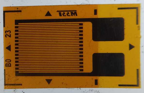
- Strain-gauge sensors: An other sensor which is also practically a resistor. A resistor’s value changes when you change its physical size. The longer the resistor the larger the resistance is, the smaller the diameter, the larger the resistance is. Strain-gauges are really thin, “stamp” like sensors that you glue to the surface of the object you want to measure. The pattern of the conductive layer on the strain-gauge is designed so that it will be very sensitive to the strain in a certain direction, but quite insensitive to perpendicular directions. As you apply force on the object you can measure the strain, and with some calibration you can calculate the force itself. The sensors are available in different variations (for example measuring two directions) and you need to connect them to a circuit called Wheatstone bridge (which is practically two voltage dividers so no worries)
- Pros:
- Straing-gauge sensors are cheap
- The Wheatstone bridge is easy to implement
- Can measure static forces
- Cons:
- The resistance value also is a function of the temperature so your measurement will be modified by the temperature of the sensor. A common trick is to use a dummy sensor (not glued to the surface) connected into the same side of the Wheatstone bridge with the real sensor. The temperature’s influence on the two sensors will be very similar thus as a proportional value it is not going to change the measurement result itself.
- You need to learn how to glue the sensor to the surface so there won’t be much tension/bias in it Also the sensor cannot be replaced from object to an other because of the glue.
- As we discussed earlier this sensor measures strain so you need some mechanical design and calibration of the sensor to measure force
- Pros:
Pressure Sensors
Not going to spend too much time here as these are practically Force Sensors.
p=F/a where p is pressure, F is the force applied on a certain area, a is the area. If you know the area where the force is applied then voila you measure pressure. There is however one thing to look out for: certain sensors measure absolute pressure value (so compared to the atmospheric pressure) and certain sensors are specifically designed to measure the pressure difference between it’s two sides – these are mostly used in process automation and such. Professional pressure sensors can also be really expensive.
Accelerometers
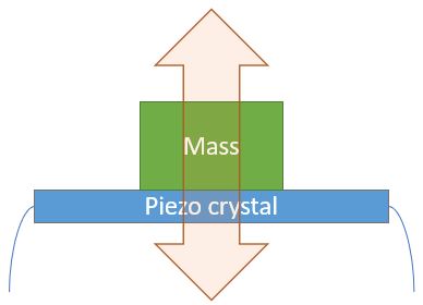
Accelerometers are sensors that measure acceleration and they are mostly used to measure the vibration of objects. Interestingly accelerometers are actually measuring force but by doing some simple math we get the acceleration. So remember how do we calculate force? F = m*a Where F is the force needed to move the object, m is the mass of the object to be moved and a is the acceleration the object achieves by the force applied on it. In our case what we need is a small object with a known mass attached to a force sensor and there you go F/m=a
There are multiple types of accelerometers based on the theory of operation.
PIEZOELECTRIC
In these sensors the object that detects force is a piezo crystal and you do the whole measurement as discussed in Force Sensors.
- Pros:
- They are versatile in various frequency ranges
- Quite common so not very expensive
- Can be lightweight so doesn’t interfere much with the vibration you want to measure
- Cons:
- As discussed with the Force Sensors they can detect dynamic changes and not good for static or very low frequency measurements
PIEZORESISTIVE
They are very similar to the Piezoelectric accelerometers but can also perform in the lower frequency ranges as piezoresistive crystals do well with static forces. In these lower frequencies you measure the displacement and not the acceleration by force.
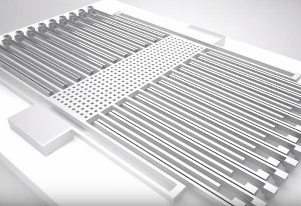
CAPACITIVE MEMS
Micro-Electro-Mechanical Systems or MEMS sensors are really state of the art technology. It means that inside a small chip a circuit is fabricated that can physically move inside. The theory of operation for the sensor is capacity measurement. Capacitors can accumulate charges and the amount of charges they can keep (so the capacitance value) depends on how close to each other are the two sides of the capacitor, how large the facing surfaces are and what is the material between the two sides (which are by the way called plates). Capacitive MEMS sensors have an internal structure where the two plates are interleaved and when you accelerate the chip itself then the internal moving parts will create a change in the capacitance value, thus you can measure acceleration. Or actually in fact you measure the force in this case too and then it is converted to acceleration via the method we discussed.
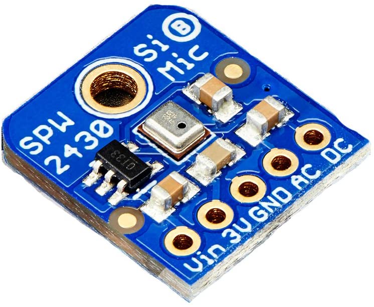
Microphones
We have covered almost everything to understand microphones: as sound waves hit the diaphragm of a microphone the pressure changes in that location and if you measure pressure fast enough you have a microphone. The newer ones are either IEPE or MEMS sensors, older models and the professional ones used in studios are condenser microphones.
IEPE, MEMS MICROPHONES
- Pros:
- Previously they were quite expensive but as technology advances they are in the middle range now
- They represent a reasonable sound quality
- Typically compact size
- Cons:
- The professional ones are still very expensive
- They are sophisticated devices so you need to pay attention not to damage them
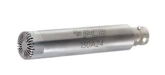
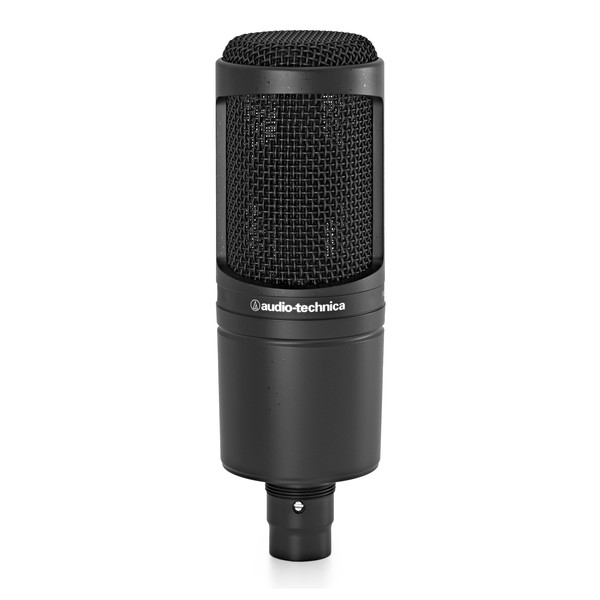
CONDENSER MICROPHONES
In condenser microphones (condenser is an other name for capacitor) the capacitor plates are the diaphragms so due to the pressure changes generated by sound waves the capacitor’s capacitance value changes and this is converted to electric signals. In order to be able to measure these signals you need to supply external voltage onto the capacitor and it certain cases this is a pretty high voltage that pose as a shock hazard so be careful. In home automation most probably you will be using IEPE or MEMS microphones.
- Pros:
- Great sound quality
- Used in studios
- Cons:
- Professional ones are really expensive
- An external voltage needs to be supplied and this might be a high-voltage
DYNAMIC MICROPHONES
They are practically inverse speakers. A coil is attached to the diaphragm and is placed around a magnet. As sound waves hit the diaphragm the coil moves back and forth in the magnetic field and thus a small voltage is generated.
- Pros:
- Quite simple technology
- Very cheap sensors are available, however expensive ones are used in studios too
- Can be harvested from old headsets and such
- Cons:
- Not great sound quality in cheap sensors
- Needs some amplification, otherwise you need to shout into them
Microphone Setups
Please note that microphones can also be categorized based on how you want to use them. This is not about studio setups but industrial use-cases. However it is unlikely that you will use your microphone in the home automation setup for such purposes this is quite an interesting read in this topic: NI Microphone Selection Guide
Angular Sensors
Angular sensors are extremely common sensors, you can find them in computer mice, printers, cars, washing machines, microwave ovens – pretty much everything that has a knob or rotating parts.
There are various types of these sensors, we are covering two basic ones.
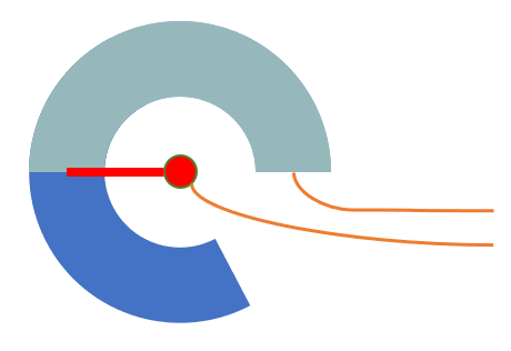
POTENTIOMETERS
As we discussed earlier a resistors resistance value is defined by various factors, in this case we are focusing on the length of the resistor. Just as a reminder: the longer the resistor the larger the resistance is. Of course you do not need to stretch the resistor but you can create a resistive strip and a conductive pin on top that touches it. The longer the pin is from the start of the strip the larger the resistance is. Not only rotational potentiometers exist but linear ones too.
- Pros:
- They are very cheap
- Simple to measure (you are measuring resistance)
- As widely used many types exists
- Give you an absolute rotational value (if at any point you measure it it will tell you the exact value)
- Cons:
- As the pin slides on the resistive strip the surface is worn off over time. This results random incorrect measurement.
- The fact that it returns an absolute value is also a limitations sometimes.
Originally potentiometers are developed so that you can adjust the resistance in an amplifier circuit, so you can adjust your volume for example and whenever you switched on your amplifier it started at a volume the potentiometer was set to. However if you use a potentiometer in an IoT application to control something there are scenarios where this behavior is not ideal: devices that are accessed by multiple other control devices. For example you set a lamp brightness with a potentiometer to 60% and after that you set the same brightness to 10% from a software UI on your phone. This will adjust the lamp brightness, but not the potentiometer’s position! So when you rotate the potentiometer again the brightness will jump to 60% and then follows your input. One workaround is to move the potentiometer with a motor to follow software requested changes. This is common is professional audio mixers and is also quite costly. The other workaround is to handle this jump from software: when the potentiometer is not aligned with the software set value and the user rotates it you just simply ignore the values until the physical and software value is matched and only after that you process the values from the potentiometer. This is common for example in low-cost home DJ solutions but is also quite uncomfortable as you need to play around with the potentiometer until you can gain the control back with it.
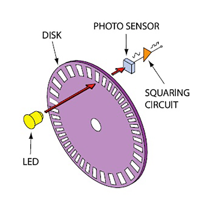
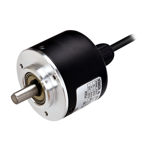
ENCODERS
The operational theory of encoders is the following: as you rotate an encoder certain pulses are generated during a rotation, these pulses are equiangular. To measure the rotation thus you only need to measure the pulses and you can calculate the rotation as an angle. For example if a sensor has 1000 pulses per one revolution and you measure 100 pulses it means 360/1000*100=36 degrees. In most cases these pulses are generated by a small light sensor which is mechanically blocked from a LED by small objects. But of course you can create encoders that are operating on other phenomenons like inductance and such.
A FEW ADDITIONAL CONSIDERATIONS FOR ENCODERS:
In the example above we measured 36 degrees but have no information about in which direction. This is solved by so called quadrature encoders. The quadrature means in this case that there is an additional encoder channel which is shifted with 90 degrees regarding the pulse trains (usually called A and B channels) generated by the encoder. So let’s see what happens in the picture below. A channel is high when there is a pulse, and low when there is no pulse. The upper part of the picture shows what happens when the encoder is rotated in one direction. Now check a rising-edge in the Channel A (so when changes from Low to High) and observe the level of Channel B: it is Low.
Now check the lower part of the picture, this shows what happens when the encoder rotates to the other direction. Now on the rising-edge of Channel A the level of Channel B is High. Thus all it takes to find out the direction is to check the Channel B level on specific Channel A edges. and to clarify: Channel A does not physically changes how pulses are generated and such between directions: simply as the rotational direction changes the rising and falling edges are swapped.

It is also important how you select the sensors with the appropriate number of pulses per revolution. If a sensor is rotating slowly and you have very few revolutions then you won’t have information about the angle between pulses for a relatively long time and also a large angle range. You will only know that the encoder is between which angles. On the other hand if you have an encoder with many pulses (so high resolution as it is called) and it rotates fast you need really fast signal conditioning. For example a hair dryer can go up to 10’000 RPM that translates to ~167 revolutions per second. If you have 1000 pulses per revolution then we are talking about a 167 kHz signal which is not straightforward to process on small devices like an ESP. So when selecting an appropriate encoder think about what is the estimated RPM range of your device and what it the angular resolution you want to achieve.
- Pros:
- Most encoders are contact-less so longevity is ensured
- Encoders can be really precise and ideal for digital processing
- There are special modes where you also count the rising- and falling-edges of both A and B channels (called x2, x4) that doubles, quadruples the resolution.
- By default they are relative sensors – so you don’t have the mismatch issues like with the potentiometers
- Cons:
- Professional ones are really expensive
- You need a device for digital signal processing to actually do the counting (if it is not integrated into the encoder then you will only get pulse trains)
- The fact that they are relative sensors are sometimes a problem too.
Making encoders absolute sensors: there are mainly two options to do that.
Z Index: you add a third channel that provides only one, short pulse per revolution and you know at which angle that pulse is. Drawback is that at a startup you need to get to it at least once before knowing where you are.
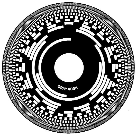
Absolute encoders: instead of 1-3 channels you have more and the combination of their values are unique for each angular positions. So for example 001010 happens at X angle, 001011 happens at Y angle. For other consideations they are designed in a way that neighboring values differ only in 1 bit/sensor value and this result a beautiful pattern (this is by the way called Grey coding).
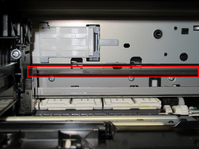
Encoders of course doesn’t need to be rotational/angular encoders. You can apply the same principle in a linear way. This is quite common in printers – this is how the cartridge cart knows where it is. You can find a plastic strip that look opaque but in fact these are very dense black lines on it. In printer terminology these are usually called timing strips.
Derived Sensors
Now that we understand a significant portion of the basic sensors we can quickly iterate through other sensors which are basically derived from the ones above. This is not going to be a very detailed description, the goal is to explain the theory of operation and to equip you with ideas to accomplish your tasks.
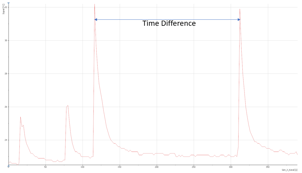
TIME DELAY SENSORS
Time delay sensors can be based on practically any other sensor and what they do is measure the time delay between specific events in the sensor’s signal. This is often accomplished in the digital signal processing and not in the sensor itself. In scientific instrumentation there are other type of time measurement devices
DISTANCE MEASUREMENT SENSORS
Distance measurement sensors can be based on multiple sensors:
- Encoders: linear encoders or rotational ones with some gearing mechanism to convert translation to rotation
- Time measurement: you transmit a physical signal and measure the time until the reflection. The transmitted signals are either light (laser for exampe), sound (ultrasound) or radio-frequency signal (radar). They cover various ranges and precisions. As light and radar signals travel much faster than ultrasound they need more sophisticated signal conditioning then ultrasonic sensors, hence they are more expensive too.
SPEED SENSORS
Speed in most cases is derived from distance measurements with the help of encoders. This is fairly simple: just measure that in a certain amount of time how far you get and the speed is easily calculated.
Of course you can use GPS devices to calculate the distance over larger areas and also radars have special speed measurement capabilities based on the Doppler-effect. This is not discussed now but a blog post will be written to into details.
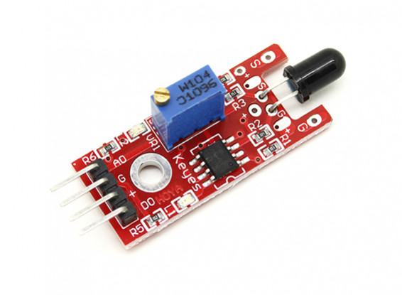
FIRE SENSORS
Fire sensors can be based on various measurement methods:
Light sensors: Flames have a characteristic wavelength so with a light sensor tuned to be sensitive in that wavelength range a flame can be detected. This is great as you can detect a fire (flame) from even a few meters
Temperature sensor: Fire is really hot so with the appropriately selected temperature measurement you can find out if a fire is present in a certain location. These sensors can cover a small area (practically need to be in touch with the fire) but can detect fire with great reliability.
Ionization sensor: Flames have a strong ionization effect and as ions conduct (to some level) electricity the presence of ions can be detected.
Integrated Sensors
You found a sensor, which doesn’t look anything like the sensors above, it can be connected to a digital input of an Arduino or ESP or to a SPI or I2C interface. What’s going on?
With technology advancements it became easier and cheaper to integrate everything (the sensor, the signal conditioning and the data acquisition device) so many cases the sensor you work with have all the measurement chain inside it and you only need to get the measurement values out of it via a communication interface. However these devices look completely different to what we discussed over here you can be sure that what’s happening inside them is exactly what we learned now.
So why does it make sense to learn all these details? Because these integrated devices usually have configurable parameters and if you understand how they work you can get a way better measurement just by setting the correct parameters.
Knowing the why