
Let’s start with something simple: we have a small printed circuit board and would like to send data from one chip to an other. They share a ground wire so we can think in a single wire to communicate over a voltage signal.
The first solution comes we might think of is connecting the input of one chip to the output of the other chip with a wire and using voltage signal. Of course we need to previously agree on what voltage level means what. In our case:
- 0 .. 0.8V means the signal is “low” so it carries a “0” as value.
- 2 .. 3.3V means the signal is “high” so it carries “1” as a value.
- Between 0.8V and 3.3V the signal shouldn’t really be, it is allowed only transitions.
From now on this is pretty straightforward: the picture below means you have received a “high” value that means “1”.
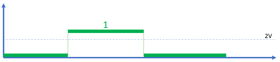
Or not? How do we know it is not “1 1”?
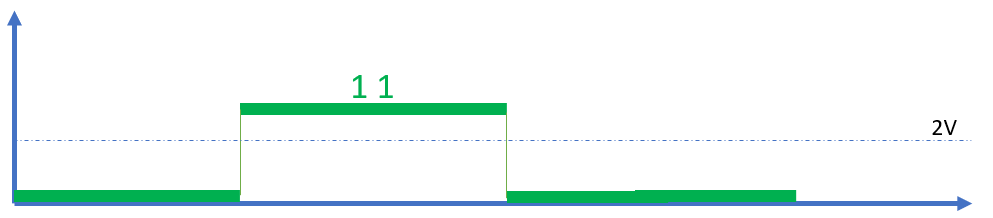
Or why not “1 1 1 1 1”?

The information we are missing is the length of a single bit in time. Without that we do not know how many leading zeros are, how many ones are and how many trailing zeros are in our signal. Before going into solutions mode let’s see how it works with more cables.
Serial Communication
If we have a single wire and we are transferring the pieces of information after one an other in time it is called serial communication. For example to transfer 8 bits you need to check the signal 8 times after each other.
Parallel Communication
If we have more than 1 wire we are talking about our communication. If we have 8 wires then we can transmit 8 bits at a single time – each wire represents one bit. This introduces an other challenge: as in electronics nothing happens exactly at the same time, but just almost at the same time we see interesting patterns during the transitions. For example originally we have 00000000 (8 pcs of zeros) and the next signal is 10000000 then the transition is straightforward as only the first bit changed. Now let’s have the same original value 00000000 but we change to 11000000. How the transition can happen? It will happen in 2 steps and it means we have two options:
- Transition 1
000000001000000011000000
- Transition 2
000000000100000011000000
So we introduced one additional value into our communications ( 10000000 or 01000000) that were not even really intended transmissions but resulted by the transition. Just like with the single wire communication it would be great to know when to sample our inputs.
Data Clocks
Data Clocks are square signals that accompany the data signal or signals and there is an agreement between the communicating parties if the falling-, the rising or both edges should be used to sample the data inputs. A rising edge is a low to high transition, a falling edge is a high to low transition in the clock signal.

Looking at this diagram our first exercise is simplified by a lot as we know when to sample the signal and now we know that our data is 001100
Without a Clock Signal
Clock regeneration
At this point it is interesting to mention that there are cases when you do not need a dedicated clock signal. We supposed that a low value means 0 and a high value means 1 but there is nothing stopping us to find other ways of coding data.
From certain types of signals and with some tricky circuits we can regenerate the clock signal from the data itself. One of the least complex implementations can be seen on the image below:

As you can see here a each bit has a defined length and a low to high transition means “1” and a high to low means “0”. With regenerative clocks you can save a clock signal wire, at the same time the processing of the signal is more complex and in the overall communication performance it has some drawbacks (communication speed for example). This was just a quick glance on Clock Regeneration.
Predefined Baud Rate
An other option to avoid the need for a dedicated clock signal is when the sender and receiver agreed on the Baud Rate in advance so they know how long is a signal segment carrying information. In this case you only need to “catch” the start of an information package and can then convert it back to information. We will discuss how to find the beginning of an information package later, in the Frames section.
Bit Rate vs Baud Rate: both Bit Rate and Baud Rate describe the speed of the information exchange. In our first example (low=0, high=1) the data coding was quite simple so an elementary data-signal segment (it is called a baud or symbol) carries 1 bit. There are however other protocols where a baud carries more than one bit information. SENT protocol for example carries 2 bits per baud. (the SENT protocol is often used in automotive sensors). So the relation between the two quantities is the following: bit rate = baud rate * no of bits per baud As an example if you set your serial port baud rate to 9600 it means it transmits 9600 symbols per second and in this case 1 baud carries 1 bit thus your bit rate is also 9600.
However note that a few bits in the communication are not effectively transferring data but needed for Framing (see later) so the effective bit rate is slightly lower than 9600. The inefficient part of the communication is called Overhead.
Now back to regular clocks.
Sampling Point
As you may remember we discussed that a wire that transfers a digital signal is actually an analog signal. The voltage level defines if it is a low or high value, this is called the Threshold. One of the characteristics of the analog signals is that they are not ideal, there are noises, the square is distorted so our clock signal’s edges position in time will have some level of uncertainty – it is called jitter. In the video below you can see it’s effect on a serial communication.
- Magenta signal: data clock, sampling is done on rising edges
- Green signal: data on the digital line
- Blue lines: sampling events defined by the clock signal crossing the threshold
- Green LEDs: data evaluation on the sampling events
- Sampling points: time-shift in the sampling events vs the data
At the beginning of this video the transitions in the data and the transitions in the clock signal are very close to each other. This means that due to the clock jitter we might have incorrectly decided values of the represented voltage level.
As we shift the clock transitions away from the data transitions our decisions became more and more stable. Ideally the sampling point should happen somehere around 50% of one bit time to make sure we sample the correct data.
In reality your data lines will have jitter too, the clock signal will be quite far from being a square signal, noise will sit on both the data and the clock. Even more talking about parallel communication the various data lines will transfer the data with various delays so our job is definitely not easy thus this sample point topic is an important thing to understand.
Framing
Now we are able transfer bits with a clock on a serial line. We know that we are transferring characters that are 8 bit long – we call the unit of transferred data a symbol. We take our theoretical device and connect it to our digital line and clock. This is what we see:
010100111010110010101010010101010101010010111101010101010101001011000110110110010100101010101010101010101011010101010101010101101010101001011101010101010101
Where does it start? Did the other end start sending when we connected to it? Where is the end of one character and where is the next one beginning?
This is where framing helps. Framing puts your useful data into a specific pattern that can provide you various things:
- Knowing where your symbol starts and ends
- In certain cases the framing itself helps in clock regeneration (not discussed here in details)
- The frame can contain fields that are automatically calculated and can tell you if the data has been corrupted during transfer (due to electric noise for example)
- In certain cases can tell you how many characters are in a frame
- Or what is the communication version (called protocol version) used during the communication
- And many other things, there are many-many communications standards
In communications where a separate clock signal is present it is also common that framing happens with the help of the clock signal itself: clock is only present when a frame is being sent and between frames the clock is a constant voltage.
Summary
So these are the basic considerations for the communications that happen over wires. There are, of course thousands of communications types: using only 1 wire, sending information back and forth over 2 wires at the same time, bandwidths from a few bits per second to 10s gigabits per second. These standards use various tricks at the same time everything is built on the principles above. Now let’s talk about a few specific implementations.